
MIDIStorm by Connor Riley

Midway through the first semester of my sophomore year at NYU, in Digital Electronics Class, I realized how easy it was to create a MIDI controller. I was amazed that we were paying so much money for MIDI controllers where you basically pay for technology that can be made for a couple dollars using a microcontroller and a few buttons and pots. MOST of these controllers are just simply a plastic enclosure with keys or buttons with nothing unique about them.
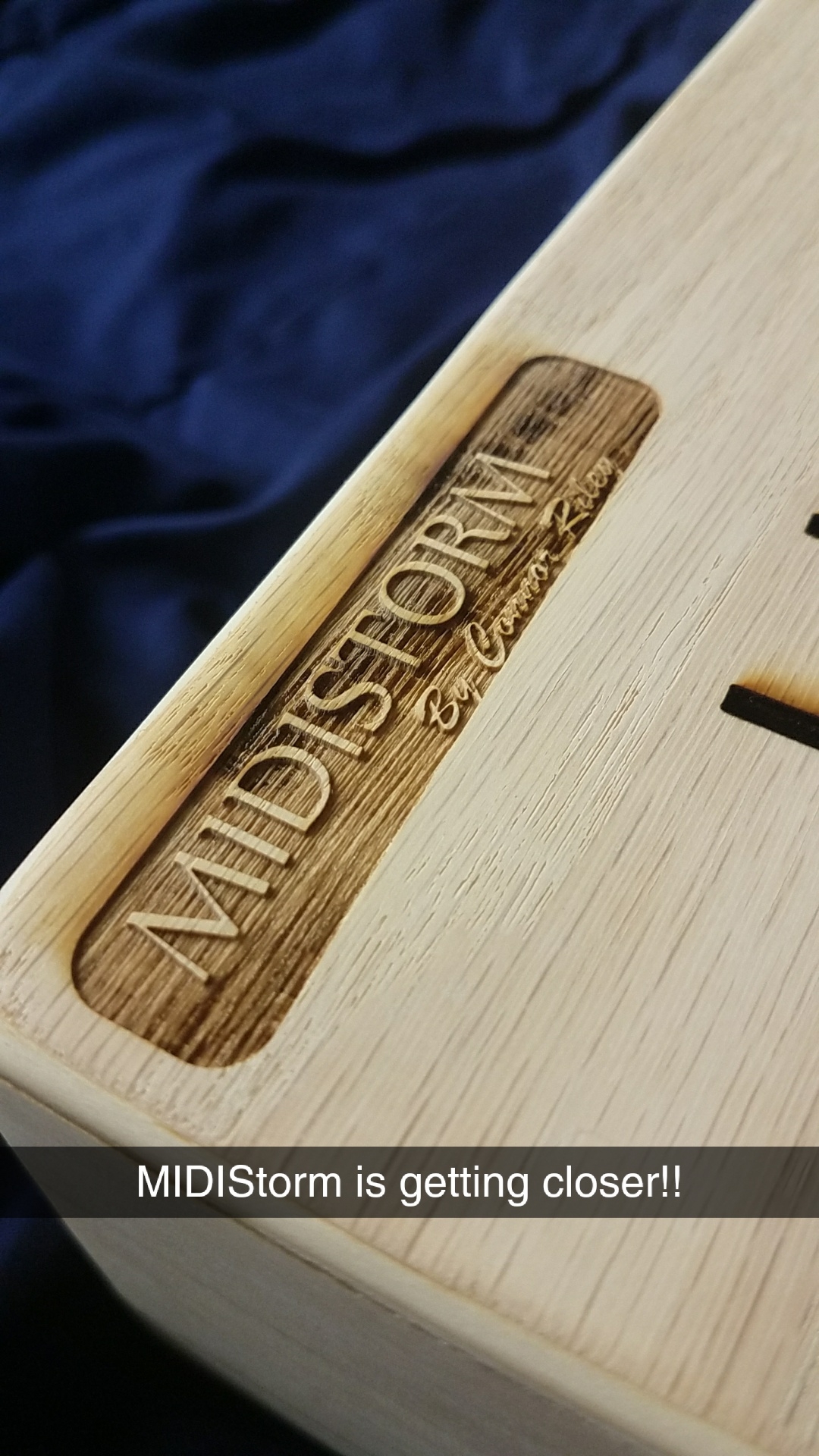
Therefore, I decided I was going to make simply a unique MIDI controller that looks really good... one might say a very AESTHETICALLY pleasing MIDI Controller... and theres nothing that looks better than a well made wood enclosure.
The Idea
So over the winter break, I worked with my wizard of a grandpa, Richard Riley Sr. (holder of many patents and a genius of DIY projects especially using wood and metal), to create a nice enclosure for what would be the MIDISTORM. We decided on:
- Oak for the enclosure with 1" wide walls and a 1/4" Oak faceplate
And before that I had decided that on the electronics side I would use:
- 8x 3.5" faders from DigiKey
- 12x LED Arcade Buttons from Adafruit
- 1x Teensy 3.5 Microcontroller
Creation

I traveled up to my grandparents house on the 28th to work with my grandfather on the project. When I got up there we got some breakfast at Bob Evan's and took a detour from working to go skating with a group of kids that he coaches just like we used to when I was a kid. After skating and a post-skate snack, we went to Lowe's, bought the wood we wanted and got to work.
1. Woodwork

We finished the cuts and assembly in about 4 hours that night and left the glue to dry overnight. The next day we sanded out he edges to create rolling edges as to please aesthetics as I was going for. Sadly, that was all I could do then though because the next step was to cut the holes for buttons, faders, and toggle switches...
2. Laser cutting/engraving
For that, I was off to the Leslie ELab Prototyping Lab to laser cut the holes. I created my template in Adobe Illustrator, did some test prints to make sure that the holes would cut right, and then continued with the stressful task of putting my beautiful, love filled box that I didn't want to f**k up, under the laser... and luckily, all went well! The holes were beautifully cut and as an added plus, the burn marks from the laser cutting were beautiful on the wood.
After that, just to further the aesthetics of the project, I laser engraved a title and labels for the toggle switches.
3. Polyurethane
After that, all of the laser work was done and I could continue to the polyurethane process. My grandpa and I had bought spray polyurethane to coat the box, protect it, and bring out that grain a bit because the grain is the aesthetic part of wood!!

This part severely annoyed my roommate because putting polyurethane coats onto untreated wood is a long process. So, over the span of about 2 weeks, I would put a coat of polyurethane onto the box, wait 72 hours for it to dry, sand it, and then do the same thing over again about 5 times. It was annoying because it took up space in our very small dorm and every other day when he came home, the room would smell like polyurethane... not that pleasant...
4. Soldering and hardware installation

Aaaaaanyway, after this long process, we got to the equally long process of soldering and installing buttons, faders, and toggles. This took a few hours but soldering is like meditation for me so it was a good process. The only annoying thing was that I was soldering on my bed, on a lap-desk next to the window as to not trigger the fire alarm... not the optimal soldering situation.
The finished product
AESTHETICCCCCCCC

Problems!!
1.
Welllllll, Connor had checked the white buttons to check the programming but not the red buttons and for some reason, the white buttons LEDs can be run on 3.3V but the red buttons NEED 5V to light up... sooooooo I had to go out to my friendly local Tinkersphere for (as suggested by my boi Steven Litt, electronics extraordinaire) a Logic Level Converter to bring my 3.3V pin voltage to a 5V signal.
2.
Multiple faders malfunctioned so I had to BUY MORE FADERS which isn't terrible because they were only about $3 each but its ANNOYING!
3.
My computer pooped itself and died in the after programming, but before uploading it to a cloud service. Luckily I had a backup on my desktop after extensive searching.